| Author |
 Topic Topic  |
|
|
gorchi

Slovenia
16 Posts |
 Posted - Jul 07 2026 : 05:26:55 Posted - Jul 07 2026 : 05:26:55


|
Hi,
we are upgrading our software from Delphi Sydney to 13.1 Florence and also upgrading the components. I read that it would be good to switch from ImageEnVect to ImageEnView and use vector layers. In our SW there is a form that does some calculations and creates a graph, basically a 6 point polygon placed over a bitmap. In the current version (Delphi Sydney, ImageEn 9.2.0 using ImageEnVect) the result looks like this:
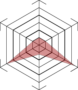
Now if I replace the component and draw a bitmap on a first layer then draw the same polygon on a second layer, the polygon gets stretched from top to bottom and from left to right. Is there some property to prevent the polygon to be stretched? Now it looks like this:
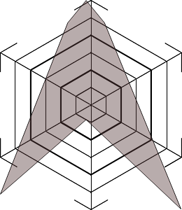
I won't even mention colour change  I guess the transparency changes the colour here... I guess the transparency changes the colour here...
Maybe if it helps, here is the code:
var
  LayerKrivulja, LayerMreza, i, iBMPsir, iBMPvis : Integer;
  sMapa, sDatotekaBMP : string;
  AP : array [0..5] of TPoint ;
  sredina, pnVogalLZ : Tpoint;
  cl_rgb : TRGB;
begin
  iBMPsir := ImageMreza.Picture.Bitmap.Width; //ImageMreza is a hidden bitmap on the form...
  iBMPvis := ImageMreza.Picture.Bitmap.Height;
  with ImageEnVGraf do
  begin
    LayerMreza := LayersAdd(ielkImage);
    CurrentLayer.Bitmap.Assign(ImageMreza.Picture.Bitmap);
    Update();

    LayerKrivulja := LayersAdd( ielkPOLYLINE );
    CurrentLayer.AspectRatioLocked := True;
    CurrentLayer.Width  := Layers[LayerMreza].Width ;
    CurrentLayer.Height := Layers[LayerMreza].Height ;

    {code for calculation of the points, fills array AP}

    with TIEPolylineLayer(CurrentLayer) do
    begin
      PolylineClosed := True;
      ClearAllPoints();
      for i := Low(AP) to High(AP) do
        AddPoint(AP[i].x, AP[i].y);//, iepbBitmap, False);
      FillColor := IzracunajBarvoLika;
      FillOpacity := (110/255);
      LineColor := clBlack;
      LineWidth := 1;
    end;
    Update();
  end;

  ImageEnVGraf.LayersMergeAll;
  ImageEnVGraf.Update();

  ImageEnVGraf.SelectionBase := iesbBitmap;
  ImageEnVGraf.Select(0, 0, iBMPsir , iBMPvis , iespReplace);
  ImageEnVGraf.LayersCreateFromSelection;
  ImageEnVGraf.DeSelect ;
  ImageEnVGraf.LayersRemove(0);
  ImageEnVGraf.LayersMergeAll;
Maybe it is important to mention, that there is no point in the array AP that touches any of the corners. For both pictures the AP has values: ((130, 125), (152, 137), (249, 219), (130, 181), (22, 212), (108, 138)), the size of bitmap (ImageMreza) is 240 x 300
Thank You for the help and best regards,
Goran |
|
|
xequte

39564 Posts |
Posted - Jul 08 2026 : 02:46:43
|
Hi Goran
The issue will be the AddPoint() call which will be scaling your points because it defaults to iepbRange (and scales the values to fit the layer size). Depending on your AP values, it should be iepbBitmap or iepbClientArea.
Can you output your AP points for me. Also, what was your equivalent code to AddPoint() that you used with IEVect.
Nigel
Xequte Software
www.imageen.com
|
 |
|
|
gorchi
Slovenia
16 Posts |
Posted - Jul 09 2026 : 02:01:13
|
Hi Nigel,
I tried also iepbBitmap (it is commented out) and in that case the results were stranger. Everything was moved to the right and bottom.
Here is the original code:
var
  LayerKrivulja, LayerMreza, iBMPsir, iBMPvis : Integer;
  AP : array [0..5] of TPoint ;
  sredina : TPoint;
  cl_rgb : TRGB;
  myRect : TRect;
begin
//ImageMreza is a hidden bitmap on the form...
  iBMPsir := ImageMreza.Picture.Bitmap.Width;
  iBMPvis := ImageMreza.Picture.Bitmap.Height;
  with ImageEnVectGraf do
  begin
    //copy bitmap to the first layer
    LayerMreza := LayersAdd;
    CurrentLayer.Bitmap.Assign(ImageMreza.Picture.Bitmap);
  end;

  //In second hidden ImageEnVect we create the polygon
  With ImageEnVectGrafTMP do
  begin
    LayerKrivulja := LayersAdd;
    Layers[LayerKrivulja].Width  := ImageEnVectGraf.Layers[LayerMreza].Width ;
    Layers[LayerKrivulja].Height := ImageEnVectGraf.Layers[LayerMreza].Height ;

    {calculation of the points}

    //Draw the polygon from those 6 points in AP
    //Calculate the colours
    Layers[LayerKrivulja].Bitmap.Canvas.Brush.Color := IzracunajBarvoLika ;

    Layers[LayerKrivulja].Bitmap.Canvas.Pen.Color := clBlack ;
    //Draw the shape
    Layers[LayerKrivulja].Bitmap.Canvas.Polygon( AP );
    //Create an layer
    MagicWandTolerance := 10000 ;
    MagicWandMode := iewGlobal ;
    MagicWandMaxFilter := false;
    SelectMagicWand( sredina.X , sredina.Y , iespReplace);
    LayerKrivulja := LayersCreateFromSelection;

    cl_rgb := Layers[LayerKrivulja].Bitmap.Pixels[1,1];
    Proc.SetTransparentColors( cl_rgb, cl_rgb, 0);
  end;
  //Transfer the polygon from ImageEnVectGrafTMP to final ImageEnVectGraf.
  //make the polygon transparent
  With ImageEnVectGraf do
  begin
    LayerKrivulja := LayersAdd( ImageEnVectGrafTMP.Layers[LayerKrivulja].Bitmap,
                                -1,
                                -1,
                                0, //ImageEnVectGraf.Layers[LayerMreza].Width,
                                0, //ImageEnVectGraf.Layers[LayerMreza].Height,
                                true);
    Layers[LayerKrivulja].Transparency := 110 ;
  end;

  ImageEnVectGraf.LayersMergeAll;

  ImageEnVectGraf.SelectionBase := iesbBitmap;
  ImageEnVectGraf.Select(0, 0, iBMPsir , iBMPvis , iespReplace);
  ImageEnVectGraf.LayersCreateFromSelection;
  ImageEnVectGraf.DeSelect ;
  ImageEnVectGraf.LayersRemove(0);

  ImageEnVectGraf.CurrentLayer.PosX := ImageEnVectGraf.Width - Round(ImageEnVectGraf.CurrentLayer.Width) div 2;
  ImageEnVectGraf.CurrentLayer.PosY := ImageEnVectGraf.Height - Round(ImageEnVectGraf.CurrentLayer.Height) div 2;
  ImageEnVectGraf.Update;
Calculation of the points is the same routine so it gives exactly the same values as I stated in my first post.
Thank You very much for the help and best regards,
Goran |
|
|
|
xequte
39564 Posts |
Posted - Jul 09 2026 : 21:30:52
|
Hi
The code below works correctly for me...
- The main issue is that if you set the width and the height of a polyline layer without calling update, then there is a pending scale that needs to occur, which is what you are seeing
- Also, as you are passing bitmap values (points of the bitmap above) you need to use iepbRange. iepbRange just means values within current the layer rect
- You can just use SetPoints( AP, iepbBitmap );
procedure TForm1.Button1Click(Sender: TObject);
const
  Image_Filename = 'NbaNVsus_IEV.bmp';      // size of bitmap (ImageMreza) is 240 x 300
  AP: array[0..5] of TPoint = (
    (X: 130; Y: 125),
    (X: 152; Y: 137),
    (X: 249; Y: 219),
    (X: 130; Y: 181),
    (X: 22;  Y: 212),
    (X: 108; Y: 138)
  );
  IzracunajBarvoLika = clYellow;
var
  LayerKrivulja, LayerMreza, i, iBMPsir, iBMPvis : Integer;
  sMapa, sDatotekaBMP : string;
  sredina, pnVogalLZ : Tpoint;
  cl_rgb : TRGB;
  ImageMreza: TIEBitmap;
begin
  ImageMreza := TIEBitmap.Create( Image_Filename );
  try
    iBMPsir := ImageMreza.Width; //ImageMreza is a hidden bitmap on the form...
    iBMPvis := ImageMreza.Height;
    with ImageEnVGraf do
    begin
      LayersClear();

      LayerMreza := LayersAdd(ielkImage);
      CurrentLayer.Bitmap.Assign(ImageMreza);
      Update();

      LayerKrivulja := LayersAdd( ielkPOLYLINE );

      // AspectRatioLocked not relevant
      // CurrentLayer.AspectRatioLocked := True;

      // Don't set the width/height because these will be calculated automatically by setting the points
      // CurrentLayer.Width  := Layers[LayerMreza].Width ;
      // CurrentLayer.Height := Layers[LayerMreza].Height ;

      {code for calculation of the points, fills array AP}

      with TIEPolylineLayer(CurrentLayer) do
      begin
        PolylineClosed := True;
        ClearAllPoints();
        for i := Low(AP) to High(AP) do
          AddPoint( AP[i].x, AP[i].y, iepbBitmap  );
          {
          // OR JUST USE
          SetPoints( AP, iepbBitmap );
          }

        FillColor := IzracunajBarvoLika;
        FillOpacity := (110/255);
        LineColor := clBlack;
        LineWidth := 1;
      end;
      Update();
    end;

    ImageEnVGraf.LayersMergeAll;
    ImageEnVGraf.Update();

    ImageEnVGraf.SelectionBase := iesbBitmap;
    ImageEnVGraf.Select(0, 0, iBMPsir , iBMPvis , iespReplace);
    ImageEnVGraf.LayersCreateFromSelection;
    ImageEnVGraf.DeSelect ;
    ImageEnVGraf.LayersRemove(0);
    ImageEnVGraf.LayersMergeAll;
  finally
    ImageMreza.Free();
  end;
end;
Nigel
Xequte Software
www.imageen.com
|
|
|
|
gorchi
Slovenia
16 Posts |
Posted - Jul 10 2026 : 07:39:35
|
Hi Nigel,
thank You very much! I had to make some small adjustment (mostly to points calculations) but basically Your code solves it. Actually the code You commented out made problems. So yes, layer size calculation made a mess.
I also stated above that the color of the polygon was strange. I understood in the help that Transparency and FillOpacity are basically the same but they are not. I set the FillOpacity to 1 and Transparency to 110 and the colors are now correct.
Now the next "lesson" shall be inserting 12 labels on the ImageEnVGraf :)
Thank You very much and best regards,
Goran |
|
|
|
xequte
39564 Posts |
Posted - Jul 10 2026 : 18:26:14
|
Hi Goran
Transparency and Opacity are the same, but FillOpacity and LineOpacity are canvas drawing properties that have a different effect on drawing.
Nigel
Xequte Software
www.imageen.com
|
|
|
| |
Topic |
|
|
|
 Search


 Switching from IE 9.2 to 15.0.0, from ImageEnVect to ImageEnView with layers